How to setup NEO 540 Output Control device
The NEO 540 provides output control functionality for managing power outputs and relays through programmable commands.
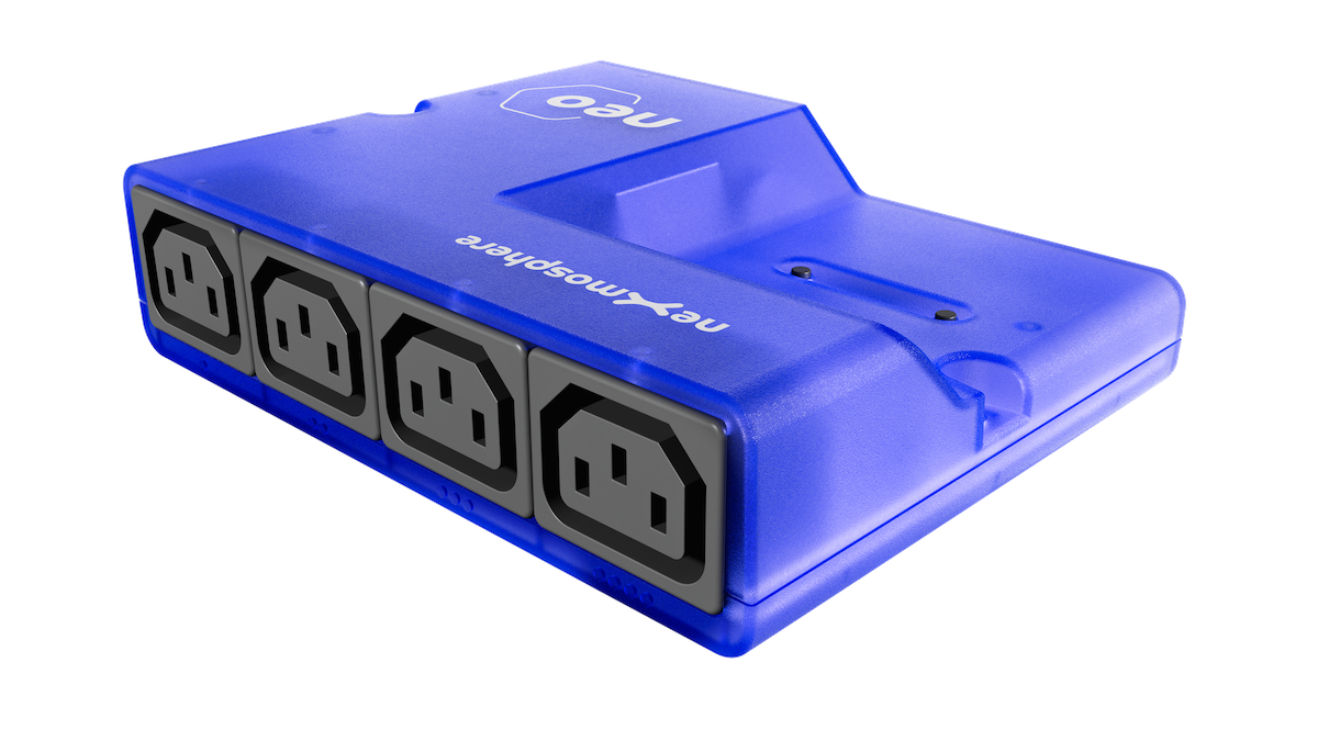
Device Overview
The NEO 540 allows you to:
- Control power outputs and relays
- Query output status
- Integrate with sensors
- Manage external devices via serial communication
Communication Requirements
- Baudrate: 115200
- Port: 2 (for BrightSign devices)
- Termination:
\r\n(carriage return + line feed) - Connection Type: USB
- All commands must end with
\r\nfor proper termination - Commands are case-sensitive
Setup & Configuration
Device Connection
- Navigate to Devices menu, then select the device where you want to use the NEO 540
- Open the device settings by clicking on the icon
OR
- Click on the device card, then select Settings tab
- Find sensor settings and configure according to your device type
If you wish to use Nexmosphere on JsCore devices, please make sure your configuration contains "port":"string" in connection, otherwise the sensors will not work.
- BrightSign devices use port 2 as communication port, so the connection must contain
"port":"2" - ANDROID AND WINDOWS DEVICES CANNOT USE THE
"port":"string", SO THE CONFIGURATION SHOULD NOT CONTAIN IT.
Windows & Android
"port":"string", SO THE CONFIGURATION SHOULD NOT CONTAIN IT.{
"services": [
{
"uid": "nexmosphere",
"type": "GENERIC",
"connection": {
"baudrate": 115200
},
"settings": {
"rules": [
{
"pattern": "(\\w\\d{3}\\w)\\[(\\d*)]\r\n",
"eventGroupIndex": 1,
"valueGroupIndex": 2
},
{
"pattern": "(\\w\\d{3}\\w)\\[(TR|TD)=UID:([A-Za-z0-9]*)]\r\n",
"idGroupIndex": 1,
"eventGroupIndex": 2,
"valueGroupIndex": 3
},
{
"pattern": "(\\w\\d{3}\\w)\\[(\\w*)=([A-Za-z0-9]*)]\r\n",
"idGroupIndex": 1,
"eventGroupIndex": 2,
"valueGroupIndex": 3
}
]
}
}
]
}
BrightSign Configuration
"port":"2" as a stringFor BrightSign devices using USB communication on port 2:
{
  "services": [
    {
      "uid": "nexmosphere",
      "type": "GENERIC",
      "connection": {
        "baudrate": 115200,
        "port": "2"
      },
      "settings": {
        "rules": [
          {
            "pattern": "(\\w\\d{3}\\w)\\[(\\d*)]\r\n",
            "eventGroupIndex": 1,
            "valueGroupIndex": 2
          },
          {
            "pattern": "(\\w\\d{3}\\w)\\[(TR|TD)=UID:([A-Za-z0-9]*)]\r\n",
            "idGroupIndex": 1,
            "eventGroupIndex": 2,
            "valueGroupIndex": 3
          },
          {
            "pattern": "(\\w\\d{3}\\w)\\[(\\w*)=([A-Za-z0-9]*)]\r\n",
            "idGroupIndex": 1,
            "eventGroupIndex": 2,
            "valueGroupIndex": 3
          }
        ]
      }
    }
  ]
}
Content
In this tutorial we will show you how to setup a content to control and manage outputs in Wallboard.
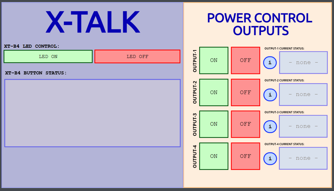
X-Talk - tests with XT-B4 push buttons
The NEO 540 can be connected with the XT-B4N6 push button interface, which works with XT-B4 push buttons. This combination allows for:

- Physical button control of outputs
- Integration of manual control with automated systems
- Enhanced user interaction capabilities
When using the XT-B4N6 interface:
- Connect the XT-B4N6 to the NEO 540
- Attach XT-B4 push buttons to the interface
- Configure button mappings in your sensor configuration
- Test button functionality with output control commands
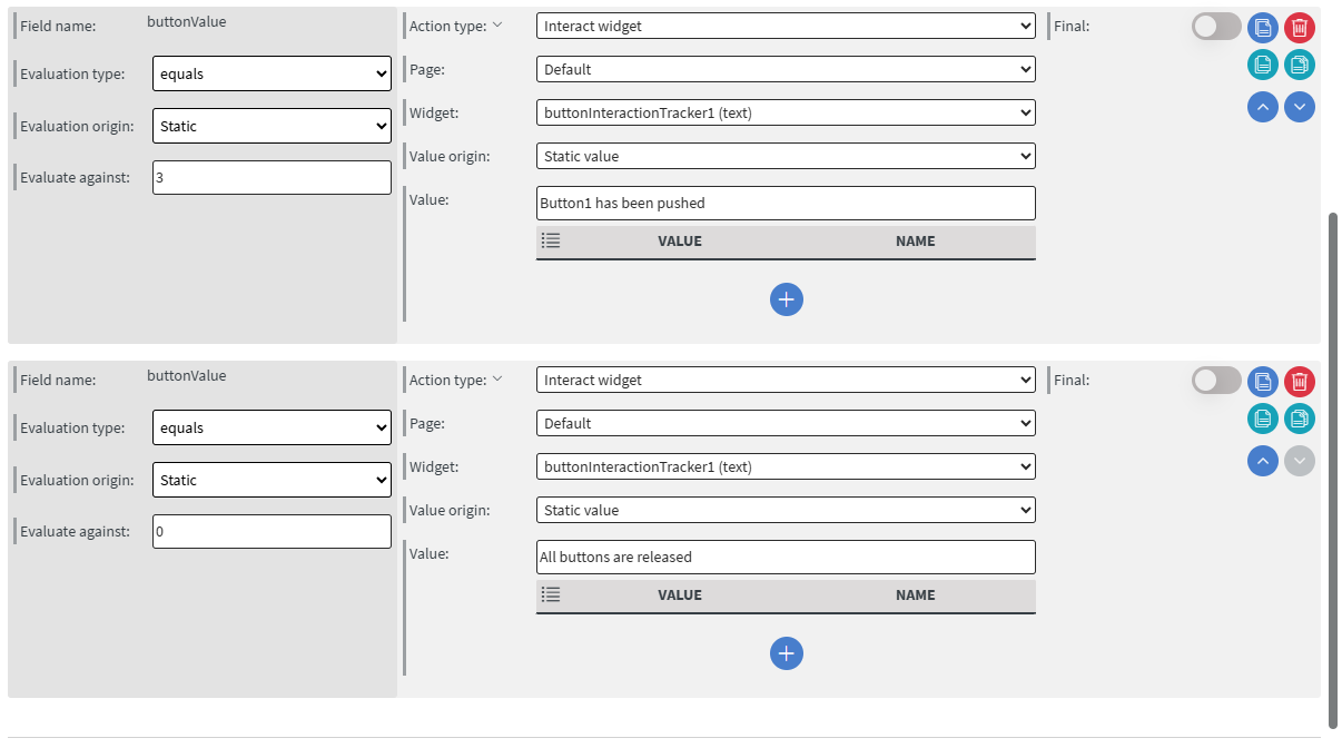
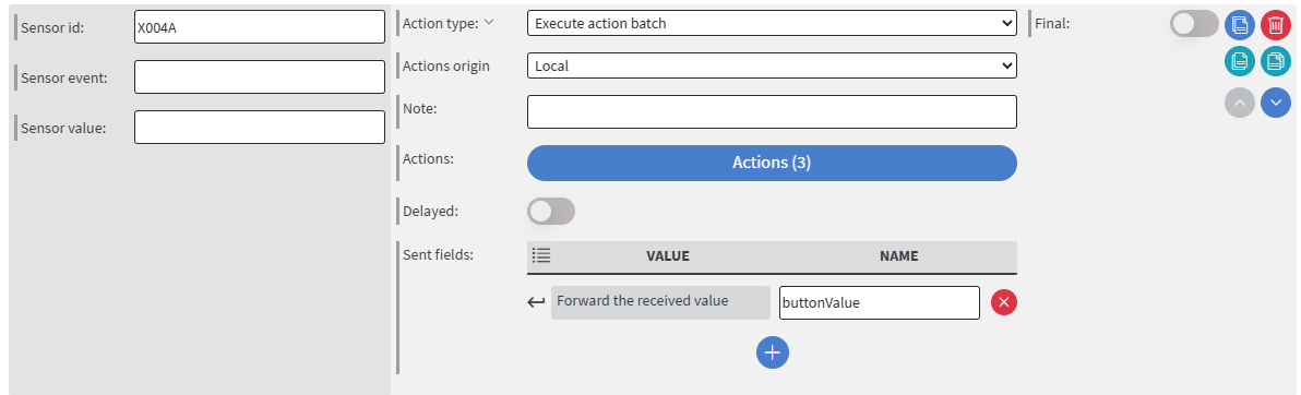
In this content we set up the following:
-
We created an action batch in the Content Properties >> Edit sensor event
- Allow specifying sensor id and Allow specifying sensor values input settings must be enabled in order to utilize this event.
-
Here we specified the sensor ID so the action will receive values from this sensor only
-
As a sent field we set received Value so everything that the sensor sends will be forwarded to the evens inside the action batch.
-
In the action batch we define the buttons pushed and released state values then set the actions that should be triggered when the device receives value from the sensor.
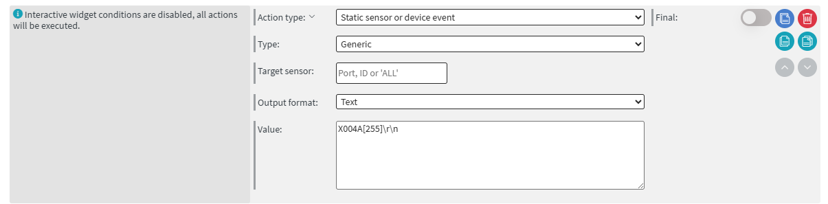
You can also send led control commands to the buttons in the following way:
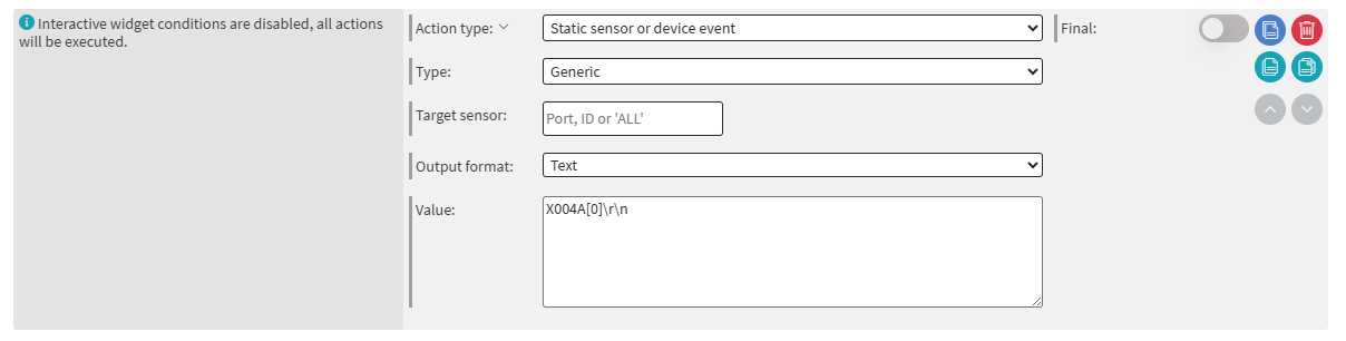 |  |
|---|
Command Format
The NEO 540 uses a specific command structure for communication:
Format: P000B[command]\r\n
Where:
-
P000Bis the standard NEO 540 device ID -
[command]is the specific output control command -
\r\nis the carriage return and line feed termination required for proper serial communicationCommand TerminationThe
\r\n(carriage return and line feed) characters are essential for proper serial communication termination. Commands without this termination may not execute correctly.
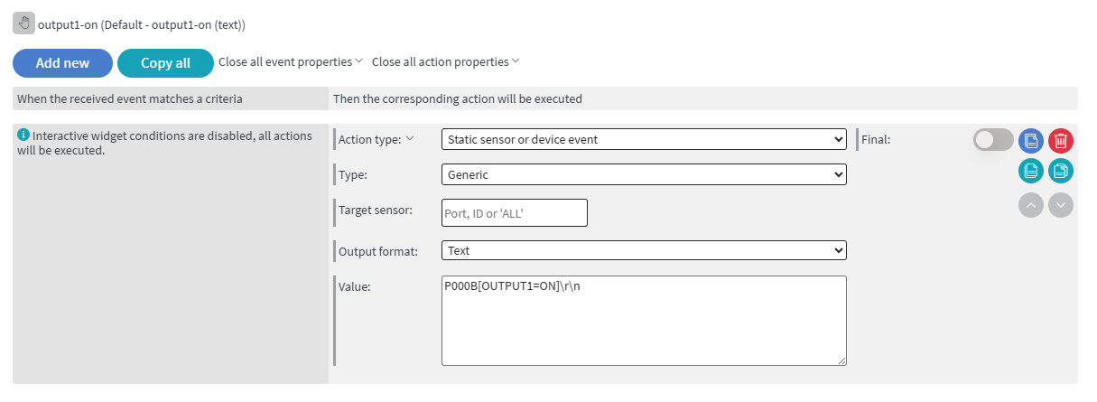
Output Control Commands
Turn Output ON
To activate output 1:
P000B[OUTPUT1=ON]\r\n
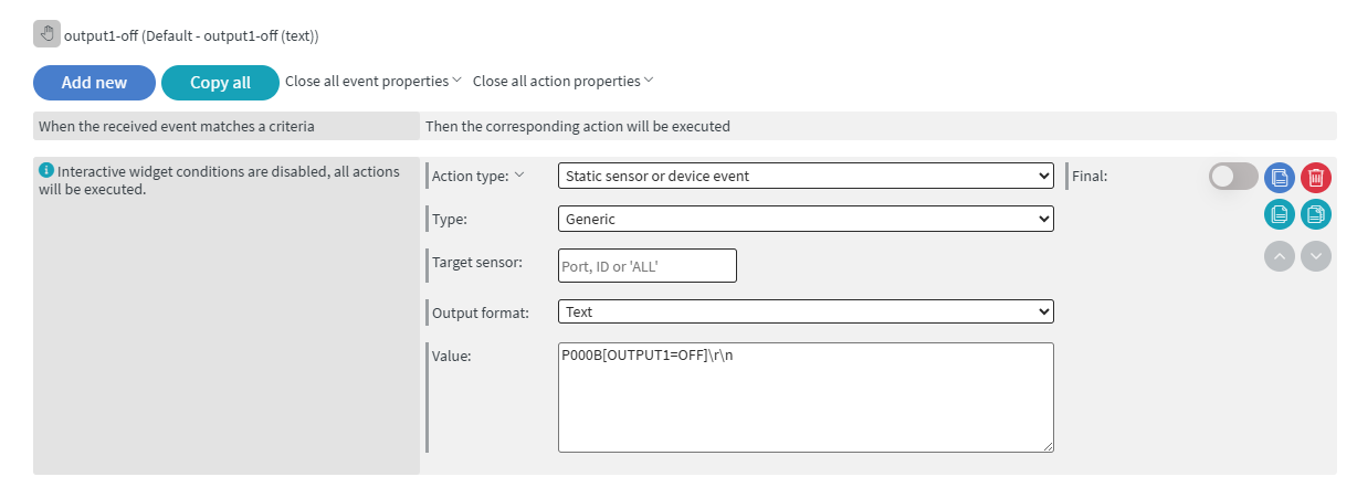
Turn Output OFF
To deactivate output 1:
P000B[OUTPUT1=OFF]\r\n
Query Output Status
To check the status of output 1:
P000B[OUTPUT1STATUS?]\r\n
Command Examples
Here are practical examples of controlling different outputs:
Output 2 Control:
P000B[OUTPUT2=ON]\r\n    // Turn output 2 ON
P000B[OUTPUT2=OFF]\r\n   // Turn output 2 OFF
P000B[OUTPUT2STATUS?]\r\n // Query output 2 status
Output 3 Control:
P000B[OUTPUT3=ON]\r\n    // Turn output 3 ON
P000B[OUTPUT3=OFF]\r\n   // Turn output 3 OFF
P000B[OUTPUT3STATUS?]\r\n // Query output 3 status
Downloadable content
NEO 540 Output control with XT-B4 push buttons | content
NOTE: Please enable Import as Content in the import modal!